High-Efficiency
LS Type
Screw Conveyors
Discover UHM’s LS Type Screw Conveyor. Feature external bearings for reliable bulk handling.
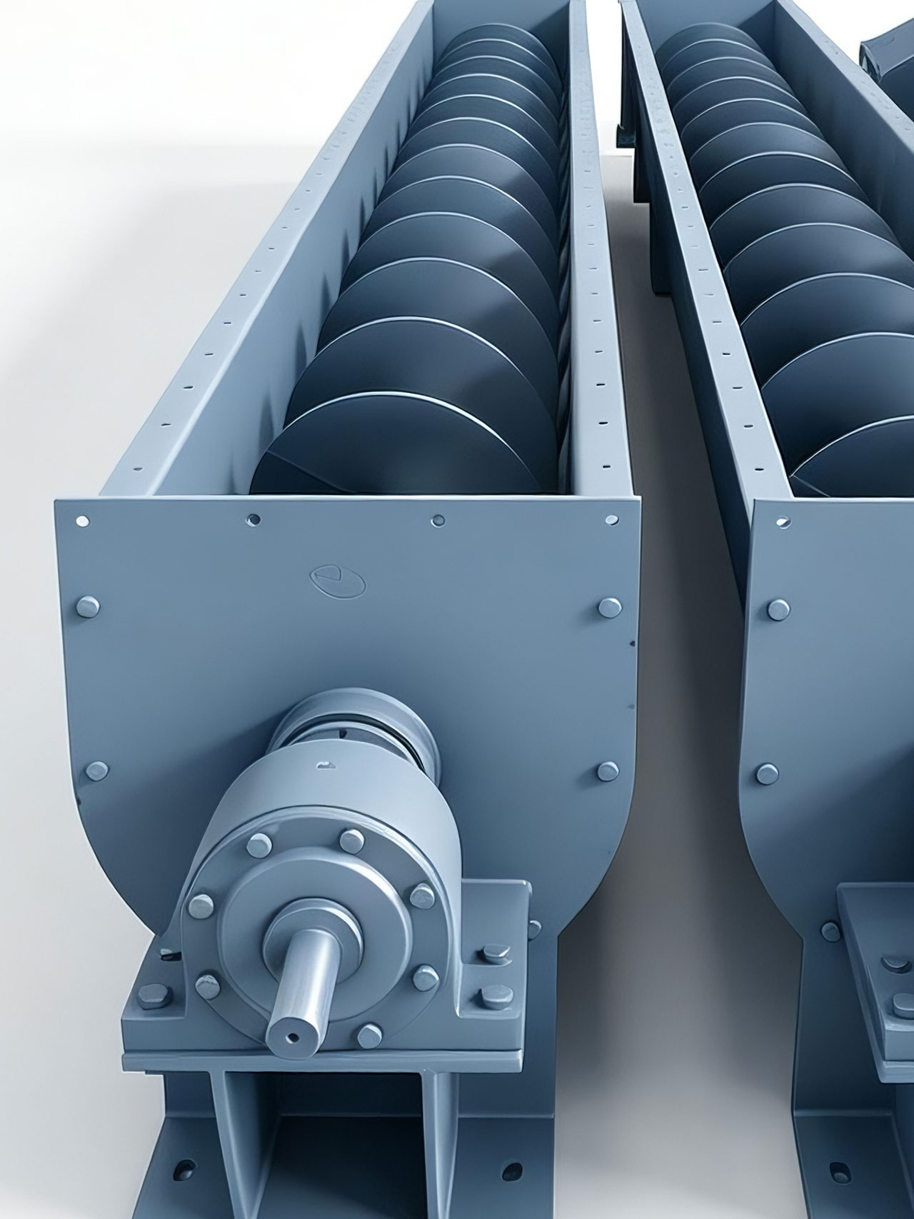
LS Type Screw Conveyors
Innovative Externalized Bearing Defenses and Cleanup/Emptying Mechanisms
The LS Type Screw Conveyor (commonly known as an industrial auger or screw conveyor) is a highly reliable continuous solid bulk mechanical progressive transport apparatus developed by UHM to eliminate traditional operational vulnerabilities. In its structural layout, this model achieves a major design breakthrough by completely moving the head and tail end bearing assemblies outside the main casing. This externalized design isolates the bearings from the material trough, eliminating dust infiltration pathways. Additionally, the discharge terminal features a mechanical sweeping scraper assembly that ensures smooth material clearing and minimizes residue dead zones, providing low operational noise, high adaptability, and streamlined maintenance access.
Interchangeable Gradation Logic Between M1 Rolling and M2 Sliding Hanger Bearings
To address intermediate hanger bearings—the most vulnerable points in multi-stage, long-distance combined conveying routes—the LS series features two interchangeable hanger bearing configurations:
- M1 Type Rolling Hanger Bearing: Utilizes a specialized 80000-series fully sealed bearing assembly backed by a rigid, dust-tight seal cap structure. This configuration is optimized for dry bulk solids where lubrication access is restricted, manual lubrication is prohibited, or oil leaks would cause secondary chemical contamination to the material stream. It delivers excellent sealing performance and extended component life for material temperatures ≤ 80 ℃.
- M2 Type Sliding Hanger Bearing: Equipped with a high-efficiency dust-tight sealing assembly, this layout is engineered for elevated material temperatures > 80℃ or damp, slightly moist materials requiring rigid structural support. It offers exceptional heat resistance and heavy-duty load impact buffering.
Single/Dual-End Drive Switching (C1/C2) and Standardized Nominal Dimension Matrices
For transmission adaptation and flexible installation spans, the LS type screw conveyor provides precise, standardized options. Screw flight diameters range from 100 mm to 800 mm across nine mainstream specifications, with standard single-unit lengths stretching from 4 meters to 70 meters. To combat torsional stress on the solid main shaft across extended lengths, the system splits into two distinct driving methods:
- C2 Method (Dual-End Drive): Mandates a synchronized dual-end drive layout for total lengths exceeding 35 meters to prevent main shaft deformation, warping, or torsional shearing failures by splitting the torsional load.
- C1 Method (Single-End Drive): Utilizes a single-end power drive layout for total conveyor lengths under 35 meters, ensuring an extremely compact footprint.
⚙️ PROCESS NOTE: LS screw conveyors require precise standardized alignments during technical selection. The total nominal length between 4 and 70 meters is engineered around a 0.5-meter step-increment. When matching factory layouts and civil engineering foundations, layouts must strictly follow these standard increments. Any non-standard lengths must be submitted during early technical phases for non-standard main shaft stress validation.
How Does It Work?
Mechanical Logic of Material Self-Weight and Wall Friction Resisting Circular Rotation
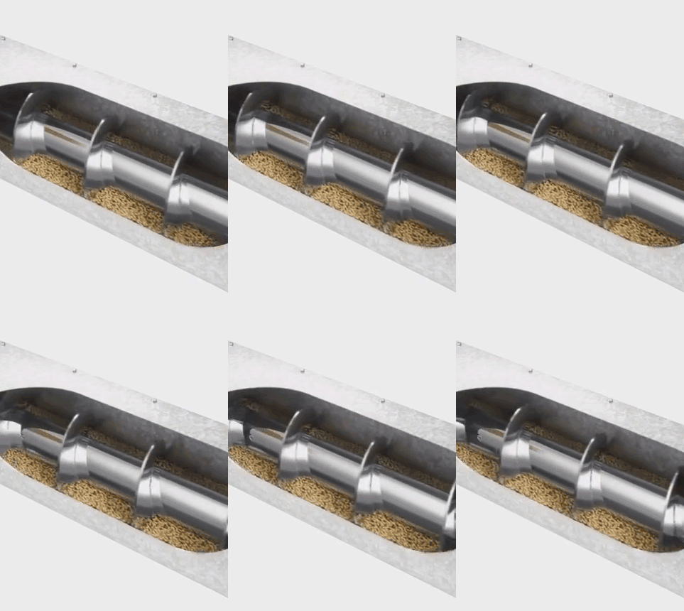
The ability of the LS screw conveyor to push powders and granules forward depends not on the screw flights clamping the material, but on the continuous balance between the material’s own gravity and the frictional resistance against the inner walls of the U-shaped trough. When the drive motor rotates the large-diameter main shaft and the Archimedes screw flights, materials falling into the bottom of the trough do not rotate 360 degrees with the screw. Constrained by gravity and wall friction, the bulk solids form a sliding plane at the bottom that resists rotational movement.
Axial Translation Conversion of Angular Flight Thrust Forces
As the screw flights rotate continuously, the angled surfaces exert a directional normal thrust against the stationary material column at the bottom of the trough. Because the material is confined by the trough walls and cannot escape outward, the lateral component of this thrust forces the material column to translate linearly along the axis of the conveyor. The material behaves like a non-rotating nut forced to move in a straight line along a spinning bolt. Under the constant drive of the main shaft speed 32 ~ 100 r/min), the product stream flows continuously from the inlet to the discharge throat.
⚙️ PROCESS NOTE: The axial advancement speed of the material stream is dictated by the main shaft RPM, but speeds must not be increased blindly. According to technical specifications, the RPM ($n$) is allowed a standard process deviation of $\pm 10\%$. Screw conveyors are not suitable for handling perishable, highly sticky, or easily caking materials. These materials instantly stick to the screw flights and main shaft, rotating 360 degrees with the assembly (preventing a sliding plane from forming) or packing tightly around the M1/M2 hanger bearings, causing immediate motor stalling and material blinding.
What Are Its Uses?
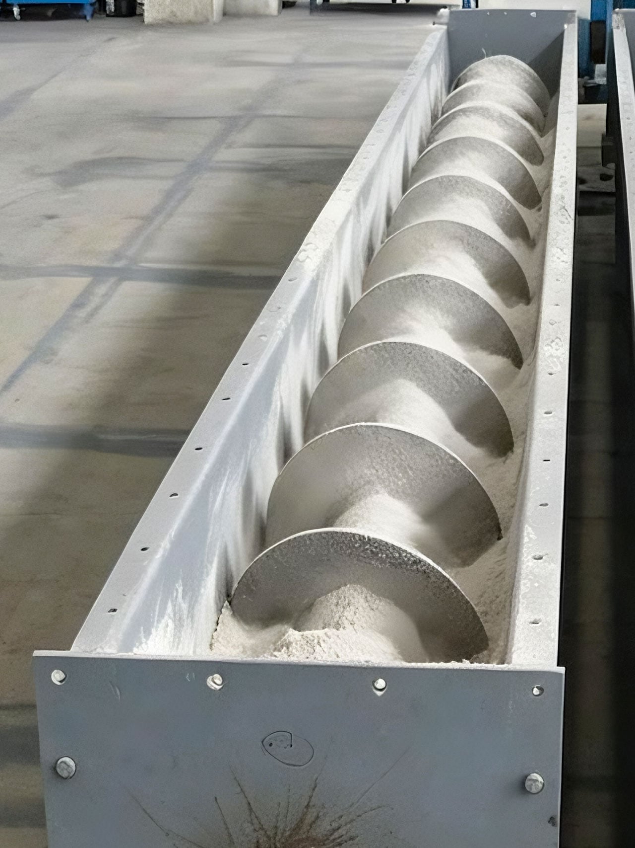
LS type screw conveyors are widely deployed across building materials, power generation, chemicals, metallurgy, aluminum-magnesium plants, coal preparation, machinery, light industry, and food processing lines. Process wise, they are optimized for horizontal or shallow-incline angles below 20 ℃ to deliver stable, low-velocity transport of loose bulk powders, granules, and small lumps at material temperatures up to 200 ℃. On cement distribution lines and fly ash batching loops, they extract cement, fertilizers, and pulverized coal from storage silos to feed gravimetric weigh scales. Beneath power plant and boiler baghouses, they transfer hot ash and sand safely. Because the assembly features a compact footprint and highly flexible inlet/outlet placement, it serves as an enclosed dosing and blending hub for multi-component grains and minerals in food processing and fertilizer plants.
⚙️ PROCESS NOTE: The rated capacities (Q) listed in technical specification tables (e.g., 62 m3/h for an LS400 at 71 r/min) are based on ideal volumetric flow rates at specific filling efficiencies. When transferring high bulk density or high friction materials (such as aluminum-magnesium powders or heavy slag), the engineering department must apply a capacity reduction factor and recalculate the required motor power to prevent main shaft torsional failure during full-load startups.
FAQ & VOTERS
How do LS screw conveyors compare against standard B series belt conveyors and tubular belt conveyors regarding incline limits and sealing performance?
These three configurations represent different technological approaches to horizontal material handling. The [Standard Belt Conveyor] is an open-air, high-speed, long-distance transport option, but its open profile provides zero dust containment and its maximum upward incline rarely exceeds 18° before materials roll backward. The [Tubular Belt Conveyor] forms an enclosed pipe to provide sealing and support complex curves, but it requires a massive structural footprint and carries high equipment capital costs, making intermediate mid-line feeding difficult. The [LS Screw Conveyor] is a highly compact, fully enclosed system designed for short-to-medium transfers. It delivers 100% dust-tight containment via rigid U-trough covers or pipe casings, fits into roughly 1/4 the space of a belt conveyor, and allows process inlets and outlets to be cut exactly where needed. However, its operating incline must be kept strictly below 20°; exceeding this angle causes severe material backflow inside the trough, dropping throughput and efficiency sharply.
Hanger bearings (M1 rolling and M2 sliding) are traditionally high-wear components. If a plant changes its material profile, how should engineers evaluate an upgrade?
Upgrading or swapping hanger bearings depends entirely on material temperature and whether lubrication exposure is permitted. If your line is initially configured to handle low-temperature, dry grains (﹤80 ℃), the M1 Rolling Hanger Bearing is the ideal choice; its internal 80000-series dust shield eliminates the need for manual greasing, keeping the product pure. However, if the process is adjusted to transfer boiler fly ash, hot fertilizers, or industrial clinker exceeding 80 ℃, the intermediate assemblies must be upgraded immediately to M2 Sliding Hanger Bearings. Under prolonged thermal conduction, the grease inside a rolling bearing dries out and carbonizes, causing immediate bearing lockup. The M2 sliding layout features wider axial clearances and high-temperature bushings to maintain shaft center alignment under thermal expansion stresses.
The technical tables specify fixed screw pitches (e.g., 355mm pitch for the LS400) and RPM limits. If downstream scales require an immediate increase in capacity, can operators double the throughput by adjusting a VFD to double the motor speed?
Absolutely not. Doing so will lead to severe main shaft shearing and material blinding. While screw conveyor capacity scales with RPM (n), the recommended maximum speeds (ranging from 100 r/min for the LS200 down to 63 r/min for the LS500) are strict design boundaries calculated from critical material velocity limits and shaft centrifugal safety parameters. Forcing the shaft to spin at double its rated speed generates excessive centrifugal force; instead of advancing faster, the bulk solids are flung outward against the U-trough walls and spin in a useless circular loop with the flights. This causes immediate material packing along the line, spiking torsional resistance and snapping the intermediate coupling bolts or twisting the main shaft entirely. If your line requires more capacity, the only safe option is to contact our engineering team to integrate a non-standard larger screw pitch or upgrade to a larger conveyor size.