K
Reciprocating Feeders
Discover UHM’s Reciprocating Feeders. High-reliability automated coal feeding
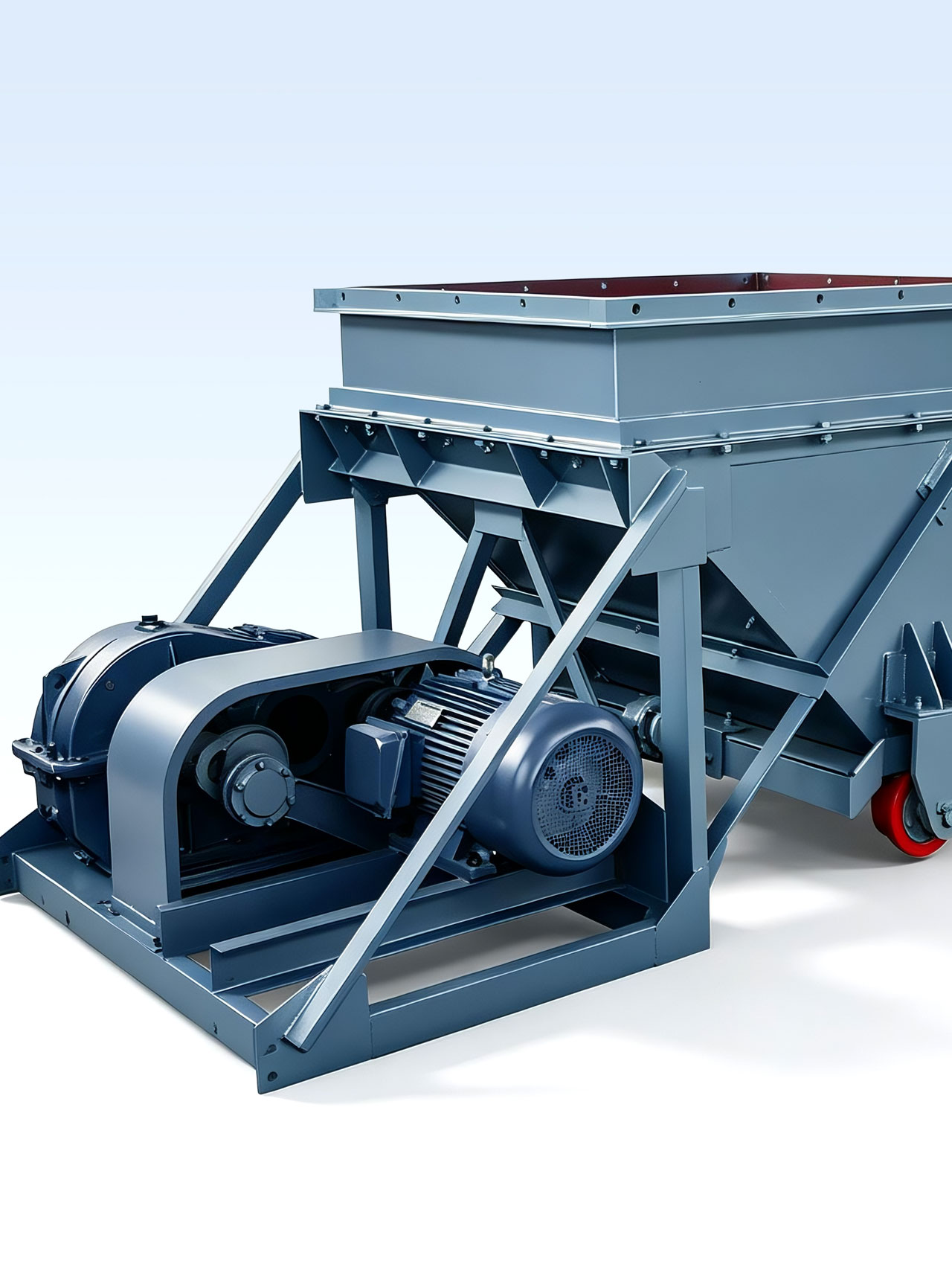
High-Reliability Volumetric Draw Hub for Bulk Coal Handing
K Type Reciprocating Feeders
Continuous and Uniform Extraction of Loose Granular Materials
The K Type Reciprocating Feeders (commonly designated as a reciprocating plate feeder) is a robust volumetric discharge apparatus engineered specifically to manage the continuous, uniform, and high-tonnage extraction of coal and other loose bulk granular materials with low abrasiveness and low moisture stickiness. Positioned directly underneath storage bunkers, track hoppers, or truck-dump reclamation pits, this feeder acts as a heavy-duty regulator that withdraws material columns and transfers them smoothly onto downstream belt conveyors, bucket elevators, or primary screening circuits.
Mechanically Resilient and Low-Profile Architecture
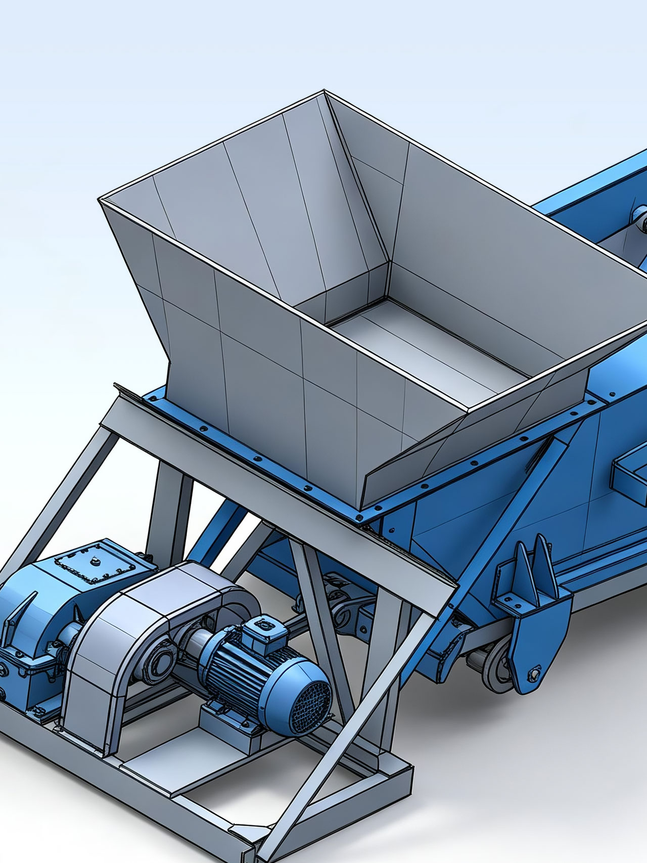
Structurally, the K series incorporates a simplified, mechanical skeleton that offers profound advantages over complex electronic vibratory drives in heavy industrial environments. The system consists of a reinforced stationary frame, a guided reciprocating bottom feed plate, an integrated drive platform, an optional heavy-gauge receiving hopper, and flow control gates. This design packs exceptional gravimetric load handling into a compact, low-profile horizontal footprint. Its heavy-duty mechanical frame absorbs the destructive static pressure of high-volume coal columns, providing coal handling facilities with an incredibly long operating life, lightweight envelope, minimal space requirement, and absolute ease of routine maintenance.
The K series reciprocating configuration is highly recommended for handling non-sticky lump minerals. By eliminating delicate external electronics and high-frequency structural stresses, it delivers a virtually bulletproof mechanical feeding solution that thrives in damp, dusty, underground mine bunkers and severe outdoor aggregate yards.
⚙️ NOTE: The K series reciprocating configuration is highly recommended for handling non-sticky lump minerals. By eliminating delicate external electronics and high-frequency structural stresses, it delivers a virtually bulletproof mechanical feeding solution that thrives in damp, dusty, underground mine bunkers and severe outdoor aggregate yards.
How Does It Work?
Crank-Link Mechanical Conversion Mechanism
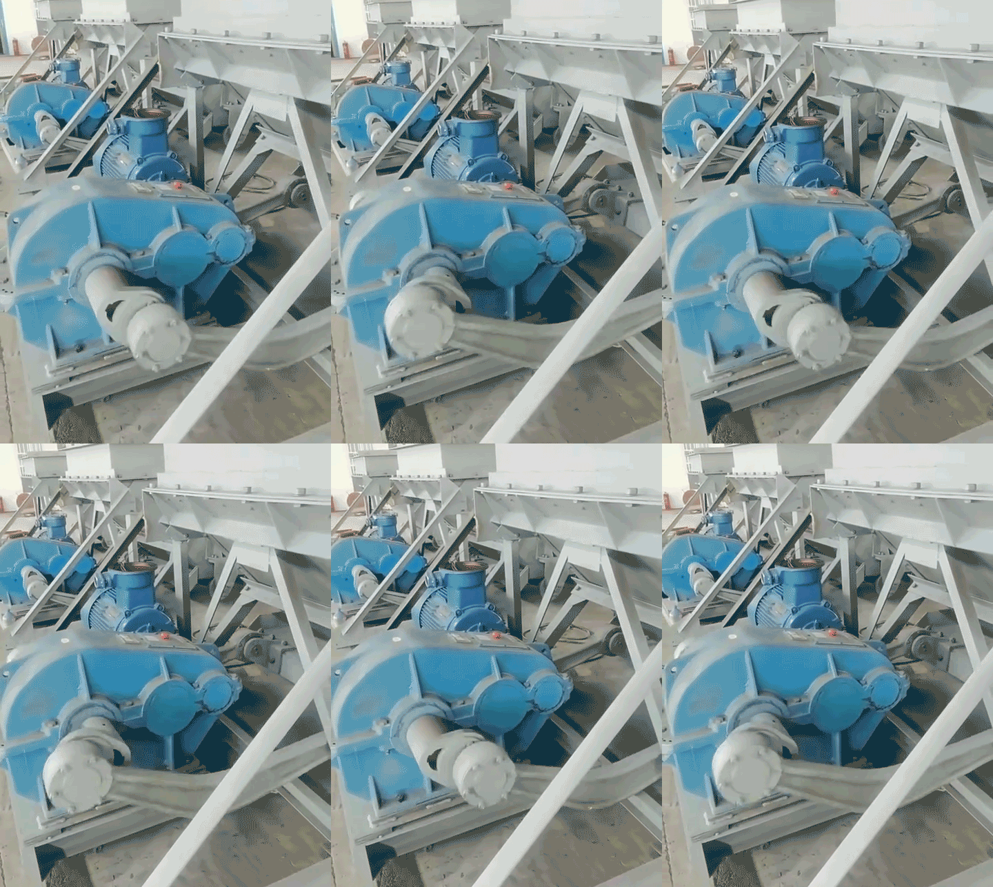
The operational kinetics of the K type Reciprocating Feeders depend on a positive mechanical crank-link conversion assembly. Power is supplied by a high-torque electric motor (often configured with explosion-proof motors like the YB series for hazardous coal mines) that couples to a heavy-duty parallel shaft gear reducer (such as the JZQ series). The gear reducer steps down the motor speed to convert high-speed rotation into high-torque low-speed output. This output drives a rugged crank wheel connected to an adjustable connecting rod linkage, transforming the continuous rotary motion of the drive shaft into a precise, low-frequency horizontal reciprocating linear stroke.
Five-Degree Sloped Linear Reciprocation and Volumetric Displacement
The connecting rod linkage is rigidly attached to the bottom feed plate (feeding trough), which sits at a fixed down-slope installation angle of 5°.
- Forward Stroke (Displacement Phase): As the crank mechanism moves through its forward cycle, it forces the sloped bottom plate to slide forward linearly on heavy-duty wear-resistant support rollers. The forward movement of the plate carries the column of coal out from the hopper opening, displacing it past the frontal discharge throat.
- Backward Stroke (Shear Phase): When the crank pulls the plate backward during the return cycle, the material layer already pulled past the hopper throat cannot return due to the static friction of the trailing coal column behind it. Instead, the plate slides back beneath the coal mass, causing the extended material to shear off and drop cleanly onto the downstream conveyor. By repeating this cyclic push-and-shear sequence, the feeder achieves a highly consistent, volumetric material flow.
The 5° downward incline of the feed plate is mathematically calculated to maximize volumetric discharge efficiency. It works alongside gravity to lower the power required during the forward push stroke while remaining shallow enough to prevent materials from naturally free-flowing or flushing over the edge when the feeder is completely stopped.
⚙️ NOTE: The 5° downward incline of the feed plate is mathematically calculated to maximize volumetric discharge efficiency. It works alongside gravity to lower the power required during the forward push stroke while remaining shallow enough to prevent materials from naturally free-flowing or flushing over the edge when the feeder is completely stopped.
What Are Its Uses?
Coal Mining Bunkers & Underground Reclamation Pits: Continuous Run-of-Mine Feed
In underground coal mines and open-cast pits, the K type feeder is widely deployed at the bottom of main underground drop chutes and surface storage bunkers. It handles raw run-of-mine anthracite and bituminous coal containing lump sizes up to 700 mm. By dampening the extreme static head-load pressure of deep storage silos, the K feeder avoids line blockages and provides a reliable, uniform stream of coal into primary crushers or heavy-duty mine haulage belts.
Coal-Fired Power Plants & Thermal Boiler Feed Systems: Reliable Fuel Blending
For coal-fired power stations, a failure in the raw coal bunkering line directly threatens boiler stability. Positioned beneath large storage bunkers, K series feeders consistently pull raw coal and feed it into pulverizer conveyor loops. Its simple mechanical adjustment ensures that blending facilities receive a continuous, uninterrupted supply of fuel particles, completely mitigating the risk of boiler starvation caused by bridging or surging.
Metallurgical Coking & Sizing Circuits: Stable Ore and Carbon Supply
In coking operations and metallurgical material preparation plants, coal and non-viscous carbon granules must be transferred evenly onto sizing screens or blending bins. The K type Reciprocating Feeders accommodates multiple structural layouts, offering configurations both with and without a receiving hopper. When equipped with adjustable flow control gates, it regulates the volume of coal layer thickness, stabilizing the raw feed entering downstream screening loops.
FAQ & VOTERS
How can operators adjust and regulate the rated throughput capacity on a K type reciprocating feeders?
The K series provides two highly reliable methods for adjusting feeding capacity. The first is mechanical stroke adjustment: by changing the pin position on the eccentric crank wheel, you can directly vary the bottom plate’s travel distance (with standard stroke settings spanning from 50 mm up to 150 mm depending on model size), where a longer stroke yields higher displacement per cycle. The second method is via the flow adjustment gate: on models configured with manual or automated vertical control gates at the hopper throat, operators can raise or lower the gate to modify the thickness of the coal layer being pulled out. All maximum capacities listed in our technical charts (ranging from 50 t/h on the compact K-0 up to 590 t/h on the heavy-duty K-4) are calibrated with the flow gate opened to its maximum limit.
What are the maximum allowable particle sizes for the K series, and how does material composition alter capacity?
The maximum allowable lump size scales directly with the physical dimensions of the feeder model. For instance, the compact K-0 can accept occasional lumps up to 250 mm (provided those oversized lumps make up less than 10% of total volume), while the largest K-4 model easily processes large coal lumps up to 700 mm. Furthermore, material composition strongly impacts capacity; as seen in our technical specifications, anthracite coal yields a higher throughput tonnage than bituminous coal under identical strokes and speeds, owing to its higher bulk density and superior internal friction characteristics during the shear phase.
What are the primary wear areas on a reciprocating plate feeder, and what maintenance steps prevent failures?
Because the K type feeder relies on sliding displacement, the primary wear zones are concentrated on the bottom feed plate liner and the under-deck support rollers. Over time, the constant sliding friction of moving abrasive coal under a heavy material column will wear down the plate surface. Maintenance teams should routinely check the thickness of the liner plates and replace them before the abrasive coal scores the main structural tray. Additionally, the support rollers beneath the plate absorb massive vertical pressures; these bearings must be greased at factory intervals to prevent seizure, ensuring they turn freely to prevent flat spots from forming on the rollers.